Firstly, add the following 4 lines to your $HOME/.profile
alias xp_start='xpra start :100 --start-child=xterm --start-via-proxy=no --opengl=yes' alias xp_list='xpra list' alias xp_stop='xpra stop :100' alias xp_attach='xpra attach :100'
To run an X11 app that persist through sessions:
0. SSH (with X11 tunneling, i.e., -X or -Y) into your server containing <your-x11-app>
1. create a new virtual xpra session, run xp_start
2. enter any tmux session or create a new tmux session, run `tmux a` or `tmux`
3. run the X11 app in tmux session with DISPLAY set to 100, run `DISPLAY=:100 <your-x11-app>`
4. inside tmux, attach the xpra session, run xp_attach. This will display the X11 app on your current screen. You can detach the xpra session by Ctrl+C. Detaching the tmux session or SSH disconnection will auto detach the xpra session as well.
Working Principle:
Xpra works by creating a virtual display (with number 100 in this example), then running <your-x11-app> on this virtual display. Since this is a virtual display, all apps running inside it will not be killed due to disconnection or session detach (unless you manually stop the display by xp_stop). When you attach this display :100, all x11-apps running inside this display will be shown on your screen, and they will persist through sessions.
Unlike ESP32, ESP8266 has only one A0 analog input port, so is it
possible to read analog input from multiple resistive sensor probes? The
answer is YES. There are several solutions that can be found online. For example, @breagan22 has provided a workable solution
by adding a diode to each sensor probe; you may also use input multiplexer chips such as ADS1015. However, those methods require additional electronic components. In this tutorial, we claim that under
the condition that all sensor probes are resistive in nature and are not
too far away from the common range of 10KΩ-300KΩ, it is possible to use a
more elegant solution without using any additional electronic
components (Method A), not even the voltage-divider resistor that is connected in series to each sensor probe.
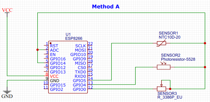
The key idea of component-less multiplexing is to make use of INPUT_PULLUP to provide voltage divider resistance (so that you do not need additional voltage divider resistors in series with each sensor probes) and use INPUT pin-mode (that has very high impedance >1MΩ) to isolate unselected sensors.
Since INPUT_PULLUP has a predefined fixed resistance of 30kΩ-100kΩ, all sensor probes have to share this same voltage divider resistance. This gives rise to Method A which requires (N+2) ports (including A0) for N sensors in total, as shown below:
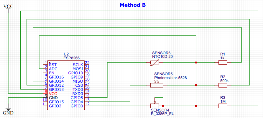
In the application scenario where all sensors need to use different voltage divider resistances or the required voltage divider resistance is too far away from the common range of 10KΩ-300KΩ provided by INPUT_PULLUP, we have to provide our own voltage divider resistors. This gives rise to Method B which requires (N*2+1) ports (including A0) for N sensors in total, as shown below.
Here are the components we used:
Any ESP8266 development board, here, we use a WEMOS D1-mini
A computer with Arduino IDE installed and a USB cable connected to the ESP8266
A breadboard with electrical wires and resistors package (optional for Method A)
GPIO
input port has very high impedance, the current is in the micro-amphere
range. By setting all these ports to INPUT, this effectively isolates
all sensor probes
Step 2: Set Common PULLUP to All Components
pinMode(GPIO14, INPUT_PULLUP);
According
to ESP8266 specification, INPUT_PULLUP has internal resistance between
30K-100K. Therefore, this effectively connects the common terminal of
all sensor probes to VCC via a resistor of 30K-100K. However, since the
other terminal of all sensor probes are connected to INPUT, no current
flows through sensor probes, none of the sensors is activated yet.
Step 3: Reading a Particular Sensor - Method 1
pinMode(GPIO5, OUTPUT_OPEN_DRAIN);
delay(500);
int value = analogRead(A0);
pinMode(GPIO5, INPUT);
Firstly,
we need to open drain on the 2nd terminal of the target sensor probe,
this effectively pull that pin to ground, allowing current to flow
through the target sensor. After waiting for some time for the voltage
to stabilize, we can read voltage from the A0 pin. At the end, remember
to disable the sensor by setting the pin mode back to INPUT.
Step 4: Reading a Particular Sensor - Method 2
pinMode(GPIO5, OUTPUT);
digitalWrite(GPIO5, LOW);
delay(500);
int value = analogRead(A0);
pinMode(GPIO5, INPUT);
The
other way to allow current to flow through the target sensor is to
write digital LOW to the other pin. The difference is that the internal
resistance between that 2nd pin and ground is lower in the case of
OUTPUT_OPEN_DRAIN. In practice, you can choose between Method 1 and 2
depending on your sensor probe's resistance characteristics. If your
sensor probes have very small resistance variation, you should use
OUTPUT_OPEN_DRAIN to increase the current so that the voltage variation
is more obvious.
Using the same principle in Method A, we set all GPIO
pins to INPUT pin mode to have very high impedance, the current is in the micro-amphere
range. This effectively isolates
all sensor probes.
Here we use digitalWrite(HIGH) and OUTPUT_OPEN_DRAIN to power up the intended sensor and use INPUT to isolate all other sensors. Similar to Method A, we can use digitalWrite(LOW) to ground the other pin with a slightly higher internal resistance:
delay(500);
int value = analogRead(A0);
pinMode(GPIO5, INPUT);
pinMode(GPIO14, INPUT);
Similarly, we sleep for some time to wait for the voltage
to stabilize, then we can read voltage from the A0 pin. At the end, remember
to disable the sensor by setting the two pins back to INPUT pin mode.
Expert computer system administrators often wants to install multiple operating systems (such as Windows 7/8/10/11/etc, and different version/flavors of Ubuntu, MX-Linux, Redhat, CentoOS, etc) and try running live systems directly without installation (for testing hardware compatibility), all using one single harddisk. For this purpose, the right tool to use is Ventoy and MX-Linux.
Ventoy allows directly copying over OS-installation ISO images onto the harddisk and booting into any one ISO image. You can select which ISO image to boot into during reboot. At the same time, the harddisk can be used to store other user data.
MX-Linux allows snap-shoting a fully-installed version of Ubuntu/Debian with all packages and configurations, so you do not need to install all useful softwares and packages again and again on each computer. Moreover, the the snap-shot ISO image can run in live mode without installation, so you can test the hardware compatibility of a fully installed OS.
Tips for Ventoy:
- specify a folder for storing boot ISO images, so that other folders (that are used for storing data) will not be scanned during Ventoy boot select: create a JSON file at /ventoy/ventoy.json , put the following configuration info in the JSON file
The Batocera OS is highly optimized for games, as a result, it has left out all other capabilities a normal operating system has. This makes life a bit difficult for users who wants both playing games and doing computing stuffs, because you need to install a separate operating system, need to buy and flash a separate microSD/SSD/USD-HDD, and reboot in order to switch between operating systems.
In this tutorial, we describe how to directly run Batocera's EmulationStation from inside Raspbian OS on Raspberry Pi 4, the same principle can be applied to PC or other systems (such as Ubuntu) as well.
This is an advance Linux tutorial, you are assumed to be familiar with basic Linux principles, file systems, Linux kernels, files and commands.
The steps are as follows: 1. Download and extract all Batocera files. i). You have already downloaded the Batocera image for RPi (either the official image from Batocera Official Download , or pre-made game pack images from Arcade Punks, etc.) This is typically an XXX.img.gz or XXX.img file. If it is gzipped, extract it first, gunzip XXX.img.gz ii). mount the image as a loop device, losetup -vfP XXX.img iii). mount the two partitions /boot (the boot partition BATOCERA) and /rootfs (the main data partition SHARE containing all roms/save-games/game-previews/etc.) mkdir -p /mnt/batocera-boot /mnt/batocera-rootfs mount /dev/loop0p1 /mnt/batocera-boot mount /dev/loop0p2 /mnt/batocera-rootfs iv). copy over all folders in these two partitions, you can use any folder other than /opt (this step is optional since you can access files on mounted loop device images directly, however it will be super slow when accessing files) cp -rfpP /mnt/batocera-boot /opt/batocera-boot cp -rfpP /mnt/batocera-rootfs /opt/batocera-rootfs
2. Mount the /opt/batocera-boot/boot/batocera SquashFS (~850MB) root file-system which contains emulationstation as well as all its dependencies. For space-speed efficiency, Batocera uses ZSTD-compressed Squash File System for its main root file-system, however, the stock Raspbian kernel does not support SquashFS. Therefore, you can either:
2a. re-compile and install the Raspbian kernel with SquashFS (ZSTD format) enabled, refer to the RPi4 stock kernel guide, make sure you backup the /boot partition before you install.
# run as root if not if [ "`whoami`" != root ]; then sudo "$0" exit 0 fi
# install tmux if not if [ ! "`which tmux`" ]; then apt-get install -y tmux fi
set -e -x -o pipefail
mount_if_not () { if [ $# -lt 2 ]; then echo "Usage: mount_if_not source target [options]" exit 1 fi if ! mountpoint -q "$2"; then mkdir -p "$2" if [ `ls "$1"/ 2>/dev/null | wc -l` -ge 1 ]; then mount --bind "$1" "$2" else mount "${@:3}" "$1" "$2" fi fi }
# 1. mount Batocera /boot mount_if_not $MOUNT_POINT-boot /batocera/boot
# 2. mount Batocera root filesystem (/batocera/rootfs) as an overlay (upper:/bool/boot/overlay, lower:/bool/boot/batocera) # 2a. create an overlay on memory mount_if_not tmpfs /batocera/overlay_root -t tmpfs -o size=256M for d in base overlay work saved; do mkdir -p /batocera/overlay_root/$d done # 2b. copy out overlay files into upper mount_if_not /batocera/boot/boot/overlay /batocera/overlay_root/saved cp -pr /batocera/overlay_root/saved/* /batocera/overlay_root/overlay/ umount /batocera/overlay_root/saved # 2c. mount batocera squashfs onto lower if [ `ls $MOUNT_POINT-squashfs/ 2>/dev/null | wc -l` -ge 5 ]; then mount_if_not $MOUNT_POINT-squashfs /batocera/overlay_root/base else mount_if_not /batocera/boot/boot/batocera /batocera/overlay_root/base fi # 2d. mount the overlay filesystem mount_if_not overlay /batocera/chroot -t overlay -o rw,lowerdir=/batocera/overlay_root/base,upperdir=/batocera/overlay_root/overlay,workdir=/batocera/overlay_root/work
# 3. mount Batocera data partition onto /userdata mount_if_not $MOUNT_POINT-rootfs /batocera/chroot/userdata
# 5. mount bind system runtime directories for p in sys proc dev run var tmp; do mount_if_not /$p /batocera/chroot/$p --bind done
# Prepare shutdown signal for returning to Raspbian if [ ! -p /batocera/chroot/signal.fifo ]; then mkfifo /batocera/chroot/signal.fifo fi echo -e "#/bin/bash\necho exit>/signal.fifo" >/batocera/chroot/sbin/shutdown chmod +x /batocera/chroot/sbin/shutdown
# Switch into Batocera, run commands in tmux so as to survive logging out the current session if [ ! "`tmux ls | grep switch_to_bato`" ]; then if [ ! -s /etc/rc.local ]; then echo -e "#!/bin/sh -e\nexit 0" >/etc/rc.local chmod +x /etc/rc.local fi if [ ! "`grep switch_to_bato /etc/rc.local`" ]; then sed -i "s:^exit:tmux new-session -s switch_to_bato -d -x 240 -y 60\nexit:g" /etc/rc.local reboot fi echo "tmux daemon has not started during boot, please reboot" exit 0 fi tmux send-keys -t switch_to_bato.0 -l "service $DISPLAY_MANAGER stop; chroot /batocera/chroot/ /etc/init.d/S31emulationstation start;read </batocera/chroot/signal.fifo; service lightdm start" tmux send-keys Enter
The above script should be run as root, or it will sudo itself. It will install tmux if not yet installed and add a line into /etc/rc.local to launch tmux server during boot if not added. It will reboot the first time it adds the tmux line into /etc/rc.local. The reason why I use tmux is because you are running this script inside the current display manager (lightdm), so if you stop the display manager, you will get logged out, all processes including this script itself will be killed before it can chroot and launch Batocera's emulationstation.
In summary, the overall underlying principle is very simple: mount all Batocera's file systems as it does (in BATOCERA/boot/initrd.gz's /init), chroot into its root folder, and start its emulationstation by /etc/init.d/S31emulationstation start. In addition, since Batocera's emulationstation acts a standalone display manager, you need to stop your current display manager (there are lightdm, gdm, xdm, sddm, etc., Raspbian uses lightdm) before entering Batocera and restart your current display manager after exiting Batocera.
PXE network boot is very useful for Retro-gaming OS such like Batocera, Recalbox, RetroPie, Lakka, etc., on Raspberry Pi. In this way, you do not need to buy any microSD/SSD/USB-HDD, you can dynamically switch to another OS image without flashing a new microSD/SSD/USB-HDD, and you can also dynamically add/remove/change game roms on network storage and play it right away. A similar but much simpler approach can be found on Batocera NAS setup, which will require you to dedicate and flash a tiny image (4GB is enough) for /boot folder and mount the entire /userdata (containing emulators and game roms) or just the ROM folder /userdata/roms from network storage (NFS or Samba) using either Wifi or LAN.
This is an advanced tutorial, you are assumed to be familiar with basic Linux working principles, SSH, and know how to manipulate files, folder and work with shell scripts. The principle can apply to any other RetroGaming OS including Recalbox, Lakka, RetroPie, etc. as well as other Raspberry Pi devices, accordingly.
Before we start, we first need to understand Batocera's standard boot sequence. For Raspberry Pi, after powering on, the eeprom boot program will initialize hardware clock and other peripherals to prepare for boot (RPi4 boot sequence). Then, it will search for boot device according to the BOOT_ORDER specified in eeprom. After found, it will load and run bootcode.bin which looks forconfig.txt. The following two lines in config.txt tell the bootloader program to load the Linux kernel in boot/linux and mount the Initial Root Directory in boot/initrd.gz (1st root file-system, ~400KB gzipped CPIO archive) as ramfs (RAM file-system, all changes will be reverted upon reboot) and run /init: kernel=boot/linux initramfs boot/initrd.gz
At the end of running /init in the /boot/initrd.gz , it will mount /boot/boot/batocera (2nd root file-system, ~850MB SquashFS) as the new root and switch root into it. Finally, it will read /boot/batocera-boot.conf to mount the data partition that contains all roms/bios/saves/screenshots/etc onto /userdata . This is where the NAS setup method can instruct Batocera to mount data partition from NFS/Samba storage other than internal storage by modifying the sharedevice field in /boot/batocera-boot.conf. However, you will still need to flash a small Batocera image to provide the /boot directory, but you can use Wifi for hosting NAS.
The steps for PXE network boot need to be done on mainly 2 or 3 sides, server side, client side (Raspberry Pi) and router side (if your home router cannot host NAS)
On the client side (change boot order to PXE network boot if no microSD is found): 1. SSH into Raspbian OS or open a terminal directly 2. (Optional) update firmware, sudo apt update && sudo apt install rpi-eeprom --upgrade 3. Go into firmware directory, cd /lib/firmware/raspberrypi/bootloader/stable/ 4. Extract boot configuration from the latest stable firmware, rpi-eeprom-config pieeprom-2021-07-06.bin > bootconf.txt 5. Edit bootconf.txt, vi bootconf.txt ; change BOOT_ORDER to at least 0x21, preferably 0x00654321 (refer to RPi4 boot order for your own preference), add or change to BOOT_ORDER=0x00654321 6. Generate updated EEPROM image, rpi-eeprom-config --out netboot-pieeprom-2021-07-06.bin --config bootconf.txt pieeprom-2021-07-06.bin 7. Flash the updated EEPROM image to EEPROM, rpi-eeprom-update -d -f netboot-pieeprom-2021-07-06.bin
On the router side (if you use router to host DHCP dhcp-boot info and use another machine to host NAS): 1. SSH into your home router 2. edit DHCP config file, vi /etc/dnsmasq.conf, append or modify into the line, dhcp-boot=bootcode.bin,192.168.1.2 (where 192.168.1.2 is your NAS server IP address), this allows DHCP server to tell RPi4 where is your TFTP server (for PXE network boot) during DHCP offer 3. restart DHCP service, service dnsmasq restart (you might need to manually kill and relaunch the dnsmasq process)
Take note that some routers does not allow SSH access or they host DHCP service in another way, then you have to figure out yourself or use your NAS server to host DHCP (if so, you will have two DHCP servers on your home intranet as every router host DHCP service, you might need to disable DHCP service on your router). Some other routers may have a DHCP settings page which allows you to specify PXE boot options, then you can do it in a nicer way.
On the server side:
This is the main and most complicated part. You need to do 4 things: A) download, mount, and extract the Batocera image; B) host /boot folder on TFTP server for PXE boot; C) host /rootfs and /boot on NFS (or Samba); D) modify configuration files and initrd.gz in /boot.
A. You have already downloaded Batocera image for RPi (either official image from Batocera Official Download , or pre-made game pack images from Arcade Punks, etc.) A1. extract the gzip file, gunzip batocera-rpi4-32-20210920.img.gz A2. mount it as a loop device, losetup -vP /dev/loop0 batocera-rpi4-32-20210920.img A3. mount its boot and data partitions: mkdir -p /mnt/boot /mnt/rootfs mount /dev/loop0p1 /mnt/boot mount /dev/loop0p2 /mnt/rootfs
A4. copy out the two folders for NFS mounting (this step is optional since you can modify and host NAS on mounted loop devices directly, however it will be super slow when accessing files); you can use any folder name other than /nfs, mkdir -p /nfs && cp -rfPp /mnt/boot /mnt/rootfs /nfs/ && chmod 777 /nfs /nfs/*
B. host /nfs/boot folder on TFTP server B1. install TFTP server, apt install tftpd-hpa B2. edit TFTP config file to set TFTP root directory, vi /etc/default/tftpd-hpa, change the line into TFTP_DIRECTORY="/nfs/boot" B3. start TFTP server, service tftpd-hpa restart
C. host /nfs/boot and /nfs/rootfs on NFS (or Samba) server C1. install Network File System kernel server, apt install nfs-kernel-server C2. edit export config, vi /etc/exports, append or modify into the 2 lines: /nfs/rootfs *(rw,sync,no_subtree_check,no_root_squash,nohide) /nfs/boot *(rw,sync,no_subtree_check,no_root_squash,nohide)
C3. restart NFS server service rpcbind restart service nfs-kernel-server restart
D. modify files in /nfs/boot D1. Create a backup and edit/nfs/boot/cmdline.txt to add or change into these settings, dev=192.168.1.2:/nfs/boot root=/dev/nfs nfsroot=192.168.1.2:/nfs/rootfs ip=dhcp D2. disable auto-resize partition, vi /nfs/boot/batocera-boot.conf, set autoresize=false D3. unpack initrd.gz into a temporary folder: mkdir -p /tmp/initrd && cd /tmp/initrd zcat /nfs/boot/boot/initrd.gz | cpio -iv D4. modify files inside /tmp/initrd as shown afterwards D5. backup and repack initrd.gz: cp /nfs/boot/boot/initrd.gz /nfs/boot/boot/initrd.gz.bak find . | cpio -ov -H newc | gzip -9 >/nfs/boot/boot/initrd.gz
D4. Modifying /tmp/initrd: The reason why PXE network boot does not work on Batocera right now is because the latest aarch64-version busybox (for early-stage file-system access) does not support NFS properly. So we need to find a statically-linked mount program that works in early stage. An example is to get it from Ubuntu for RPi. You can download "Ubuntu Server 20.04.3 LTS", use losetup to mount its boot folder as before and find its initrd (it's in /<mount-point>/boot/initrd.img ), extract the LZ4-compressed CPIO archive (cd /tmp/initrd2 && lz4 -dc /<mount-point>/boot/initrd.img | cpio -iv) into some temp folder (/tmp/initrd2). Find the mount program that can mount nfs:
root@dell:/tmp/initrd2# file bin/nfsmount bin/nfsmount: ELF 64-bit LSB executable, ARM aarch64, version 1 (SYSV), statically linked, interpreter /lib/klibc-unVzPS-prFh5518UkFjYOJInn9c.so, BuildID[sha1]=bc89c69698500f3b17c10a6ff8718e162fbd5bd3, stripped
Copy out both bin/nfsmount and its dependency library /lib/klibc-unVzPS-prFh5518UkFjYOJInn9c.so into /tmp/initrd/bin and /tmp/initrd/lib respectively.
Now, we need to edit the init script, /tmp/initrd/init: - in the do_mount() function, add the following nfsmount command after the 1st mount command failed, if nfsmount -o ro "${1}" /boot_root; then return 0; fi - in "# read the parameters" section, add reading nfsroot parameter inside the case statement, nfsroot=*) nfsroot=${param#nfsroot=};; - before "# moving current mounts" section, add the following lines to do nfsmount if nfsroot is specified: if test -n "${nfsroot}" then mkdir -p /new_root/userdata nfsmount -o rw "${nfsroot}" /new_root/userdata rm -f /new_root/etc/init.d/S11share fi
The last rm -f /new_root/etc/init.d/S11share line is to prevent Batocera from remounting /userdata according to /nfs/boot/batocera-boot.conf, because the built-in busybox mount program does not work for NFS.
This tutorial is on how to make Batocera
display work on small LCD screens such as MHS35 (as shown below) for
Raspberry Pi 4. The same principle can be applied to other models of LCD
display as well as other Raspberry models.
This is an advanced tutorial, you are assumed to be familiar with
basic Linux working principle, can SSH into Raspbian and Batocera, copy
files in and out, and have already made your small LCD screen working on
Raspbian OS.
The steps are mainly divided into 2 categories, kernel level and user level:
Kernel level
a) Copy the overlay driver module files (e.g., for MHS35 LCD screen, mhs35.dtbo, mhs35-overlay.dtb) into /boot/overlays/ folder from Raspbian’s /boot/overlays/ folder
b) Create a new folder /boot/overlays.bak/ and copy /boot/overlays/vc4-kms-v3d-pi4.dtbo into it for backup; then copy /boot/overlays/vc4-fkms-v3d.dtbo into /boot/overlays/vc4-kms-v3d-pi4.dtbo , this is to force Batocera to load the LCD’s 3D driver instead of HDMI’s 3D driver
c) Adjust settings in /boot/config.txt and /boot/cmdline.txt
i) In /boot/config.txt , add the LCD driver line dtoverlay=mhs35:rotate=90 ; add the GPU 3D acceleration line dtoverlay=vc4-fkms-v3d,noaudio ; you can optionally add the display resolution lines, you can use either fixed resolution (e.g., 800×480):
Or flexible resolution (with initial resolution, e.g., 85 for 1280×720, please refer to Raspberry Pi official link):
hdmi_group=2 hdmi_mode=85 hdmi_drive=2
ii) In /boot/cmdline.txt , append console=serial0,115200 fbcon=map:10 fbcon=font:ProFont6x11 to the line (don’t create a new line), these optional settings are for console display
User level
a) Create a new folder (e.g., mybin ) inside the system folder, transfer the frame-buffer copier program, /usr/local/bin/fbcp, into that folder
b) Copy the dependent libraries (such as libvchiq_arm.so.0, libvcos.so.0, etc.) into the folder; you can get the dependency libraries of a Linux executable by running ldd -v fbcp in Raspbian
c) Create the auto-start script /system/custom.sh (if absent), add the line to run fbcp, LD_LIBRARY_PATH=/userdata/mybin /userdata/mybin/fbcp & into the script
Take note that if you SSH into Batocera to modify things, the /boot folder is mounted as read-only, if you want to modify files, you need to remount it as read/write, mount /boot -o remount,rw
; the root folder (excluding /userdata) is ramfs (file-system in
memory), any change will be reverted upon reboot, so all new files or
modifications must be in /userdata folder, which is the data partition (/media/<your-username>/SHARED) if you mount the SD card in a PC.
PXE network boot is becoming a very powerful tool nowadays. It can be used for setting up a large cluster of identical-purpose computers (e.g., computer access room for students); it can also be used to boot into a selected image for small Internet-based devices, e.g., Raspberry Pi running Raspbian, Ubuntu, RetroPie, Batocera, Lakka, Recalbox, Manjaro, Gentoo, or etc. You don't have to buy many big microSD cards, one for each image, neither do you need to flash the image onto the microSD card every time.
The setup process involves two sides, server side (for hosting the image) and client side (for PXE booting into the hosted image via network).
Server side:
1. Configure the DHCP server to tell the boot server's IP address. Add the following line into /etc/dnsmasq.conf and restart dnsmasq service
dhcp-boot=kernel8.img,192.168.50.2
where kernel8.img is the Stage-1 boot image file (such as grubnetx64.efi.signed, grubx64.efi, bootmgr.efi); 192.168.50.2 is the TFTP server IP address (see below).
2. Host PXE boot folder using TFTP. Install and start tftpd-hpa, its configuration file is in /etc/default/tftpd-hpa . You can set the TFTP root folder location which contains the boot directory including the boot image file.
Most of the time, the machine that hosts DHCP server can also host TFTP (since TFTP is a built-in feature of dnsmasq), so Step 1 and 2 can be combined, you can specify tftp-root in /etc/dnsmasq.conf, and the IP address field in dhcp-boot can be left out. Take note that all routers host a DHCP server by themselves, so if there are more than one DHCP servers in the same network, it might cause IP conflict.
3. Host operating system's root folder (e.g. /nfs/rootfs) and boot folder (e.g., /nfs/boot) using NFS
4. Modify /nfs/boot/cmdline.txt , append the string root=/dev/nfs nfsroot=192.168.50.2:/nfs/boot,vers=3 rw ip=dhcp onto the same line, this is to ask the kernel to load root filesystem from NFS instead of from local storage
5. Modify /etc/fstab in the hosted root filesystem to mount NFS as root instead of /dev/sd* or /dev/nvm*, etc.
Client side:
1. Set boot order. You must configure the boot order in BIOS (for PC) or eeprom (for Raspberry Pi) to boot from PXE if previous boot options all fail.
1a. On Raspberry Pi, extract boot config info by running:
  cd /lib/firmware/raspberrypi/bootloader/stable/
  rpi-eeprom-config pieeprom-2021-07-06.bin > bootconf.txt
1b. Edit bootconf.txt, change BOOT_ORDER to at least 0x21, preferably 0x0365421
2. You must make sure PXE network boot is currently the first available boot option (by plugging out hard-disks or microSD cards if their boot order is prior to PXE netboot)