Unlike ESP32, ESP8266 has only one A0 analog input port, so is it possible to read analog input from multiple resistive sensor probes? The answer is YES. There are several solutions that can be found online. For example, @breagan22 has provided a workable solution by adding a diode to each sensor probe; you may also use input multiplexer chips such as ADS1015. However, those methods require additional electronic components. In this tutorial, we claim that under the condition that all sensor probes are resistive in nature and are not too far away from the common range of 10KΩ-300KΩ, it is possible to use a more elegant solution without using any additional electronic components (Method A), not even the voltage-divider resistor that is connected in series to each sensor probe.
The key idea of component-less multiplexing is to make use of INPUT_PULLUP to provide voltage divider resistance (so that you do not need additional voltage divider resistors in series with each sensor probes) and use INPUT pin-mode (that has very high impedance >1MΩ) to isolate unselected sensors.
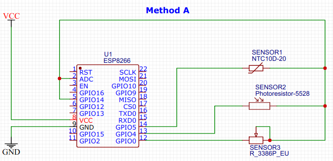
Since INPUT_PULLUP has a predefined fixed resistance of 30kΩ-100kΩ, all sensor probes have to share this same voltage divider resistance. This gives rise to Method A which requires (N+2) ports (including A0) for N sensors in total, as shown below:
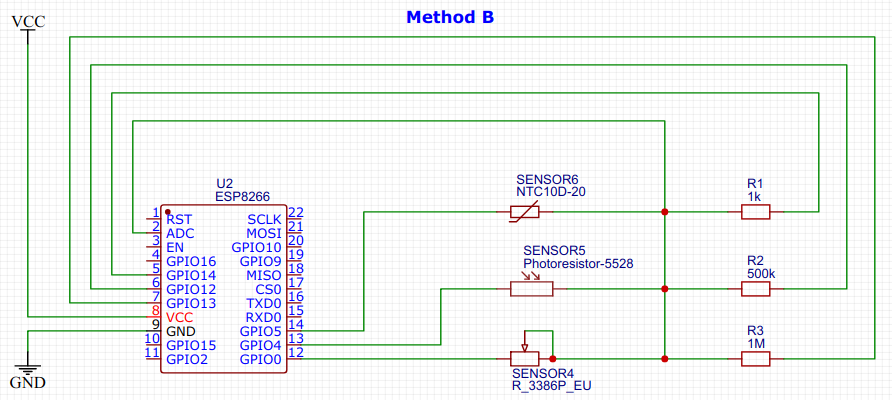
In the application scenario where all sensors need to use different voltage divider resistances or the required voltage divider resistance is too far away from the common range of 10KΩ-300KΩ provided by INPUT_PULLUP, we have to provide our own voltage divider resistors. This gives rise to Method B which requires (N*2+1) ports (including A0) for N sensors in total, as shown below.
Here are the components we used:
- Any ESP8266 development board, here, we use a WEMOS D1-mini
- A computer with Arduino IDE installed and a USB cable connected to the ESP8266
- A breadboard with electrical wires and resistors package (optional for Method A)
- Sensor probe 1, a thermistor
- Sensor probe 2, a photo-resistor
- Sensor probe 3, a variable resistor
- Multi-meter (optional)
Method A
Step 1: Initialize All GPIO Ports As INPUT
pinMode(GPIO0, INPUT);
pinMode(GPIO4, INPUT);
pinMode(GPIO5, INPUT);
pinMode(GPIO14, INPUT);
GPIO input port has very high impedance, the current is in the micro-amphere range. By setting all these ports to INPUT, this effectively isolates all sensor probes
Step 2: Set Common PULLUP to All Components
pinMode(GPIO14, INPUT_PULLUP);
According to ESP8266 specification, INPUT_PULLUP has internal resistance between 30K-100K. Therefore, this effectively connects the common terminal of all sensor probes to VCC via a resistor of 30K-100K. However, since the other terminal of all sensor probes are connected to INPUT, no current flows through sensor probes, none of the sensors is activated yet.
Step 3: Reading a Particular Sensor - Method 1
pinMode(GPIO5, OUTPUT_OPEN_DRAIN);
delay(500);
int value = analogRead(A0);
pinMode(GPIO5, INPUT);
Firstly, we need to open drain on the 2nd terminal of the target sensor probe, this effectively pull that pin to ground, allowing current to flow through the target sensor. After waiting for some time for the voltage to stabilize, we can read voltage from the A0 pin. At the end, remember to disable the sensor by setting the pin mode back to INPUT.
Step 4: Reading a Particular Sensor - Method 2
pinMode(GPIO5, OUTPUT);
digitalWrite(GPIO5, LOW);
delay(500);
int value = analogRead(A0);
pinMode(GPIO5, INPUT);
The other way to allow current to flow through the target sensor is to write digital LOW to the other pin. The difference is that the internal resistance between that 2nd pin and ground is lower in the case of OUTPUT_OPEN_DRAIN. In practice, you can choose between Method 1 and 2 depending on your sensor probe's resistance characteristics. If your sensor probes have very small resistance variation, you should use OUTPUT_OPEN_DRAIN to increase the current so that the voltage variation is more obvious.
Method B
Step 1: Initialize All GPIO Ports As INPUT
pinMode(GPIO0, INPUT);
pinMode(GPIO4, INPUT);
pinMode(GPIO5, INPUT);
pinMode(GPIO12, INPUT);
pinMode(GPIO13, INPUT);
pinMode(GPIO14, INPUT);
Using the same principle in Method A, we set all GPIO pins to INPUT pin mode to have very high impedance, the current is in the micro-amphere range. This effectively isolates all sensor probes.
Step 2: Power up the intended sensor
pinMode(GPIO14, OUTPUT);
digitalWrite(GPIO14, HIGH);
pinMode(GPIO5, OUTPUT_OPEN_DRAIN);
Here we use digitalWrite(HIGH) and OUTPUT_OPEN_DRAIN to power up the intended sensor and use INPUT to isolate all other sensors. Similar to Method A, we can use digitalWrite(LOW) to ground the other pin with a slightly higher internal resistance:
pinMode(GPIO14, OUTPUT);
digitalWrite(GPIO14, HIGH);
pinMode(GPIO5, OUTPUT);
digitalWrite(GPIO5, LOW);
Step 3: Reading a Particular Sensor
delay(500);
int value = analogRead(A0);
pinMode(GPIO5, INPUT);
pinMode(GPIO14, INPUT);
Similarly, we sleep for some time to wait for the voltage to stabilize, then we can read voltage from the A0 pin. At the end, remember to disable the sensor by setting the two pins back to INPUT pin mode.